
Deconstructing Network Communication: How Your Simple JSON Request Traverses Seven Layers of the OSI Stack
A Engineer's Guide to Understanding Backend-to-Backend Data Flow Through the OSI Model

When you send a simple JSON payload {"message": "Mohit"} from Backend A to Backend B and receive {"message": "Mishra"} in return, you're witnessing one of the most elegant orchestrations in computer science. This seemingly trivial exchange involves seven distinct layers of processing, each with its own responsibilities, protocols, and failure modes.
As engineers, we often take this for granted, but understanding the intricate dance happening beneath our HTTP requests is crucial for debugging network issues, optimizing performance, and designing resilient systems.
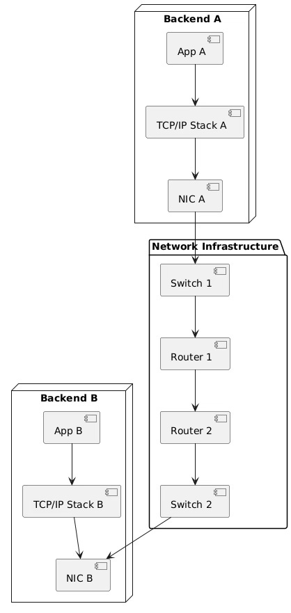
The Complete Request Flow Architecture
Layer-by-Layer Breakdown: The Downward Journey (Backend A)
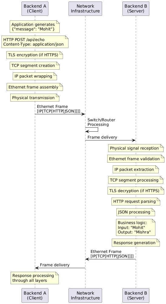
Layer 7: Application Layer - Where Business Logic Begins
The journey starts in your application code. When Backend A decides to send the JSON request, several critical operations occur:
Protocol Selection and Message Formation:
Your application (Node.js, Spring Boot, Go service) constructs the HTTP request
HTTP method selection (POST for our JSON payload)
Header construction:
Content-Type: application/json,Content-Length: 20URI path resolution:
/api/echoor similar endpoint
Critical Implementation Details:
POST /api/echo HTTP/1.1
Host: backend-b.internal.company.com
Content-Type: application/json
Content-Length: 20
Connection: keep-alive
User-Agent: Backend-A/1.0

{"message": "Mohit"}
The application layer doesn't concern itself with how this data will travel across the network. It simply formats the request according to HTTP specifications and passes it to the OS socket layer.
Error Handling at This Layer:
Invalid JSON syntax detection
HTTP status code interpretation
Application-specific timeout handling
Layer 6: Presentation Layer - Data Transformation and Security
This layer handles the critical task of preparing data for network transmission:
Character Encoding:
UTF-8 encoding of the JSON string
Byte representation:
7B 22 6D 65 73 73 61 67 65 22 3A 20 22 4D 6F 68 69 74 22 7D
Compression (Optional):
If gzip compression is negotiated via
Accept-Encoding: gzipCompression ratio for JSON is typically 60-70%
Encryption for HTTPS: When using HTTPS, this layer performs TLS operations:
Cipher suite negotiation (e.g., TLS_AES_256_GCM_SHA384)
Session key derivation
Symmetric encryption of the HTTP payload
MAC (Message Authentication Code) generation
TLS Record Structure:
TLS Record Header (5 bytes):
- Content Type: 0x17 (Application Data)
- Version: 0x0303 (TLS 1.2)
- Length: Variable
Encrypted Payload:
- Original HTTP request + padding
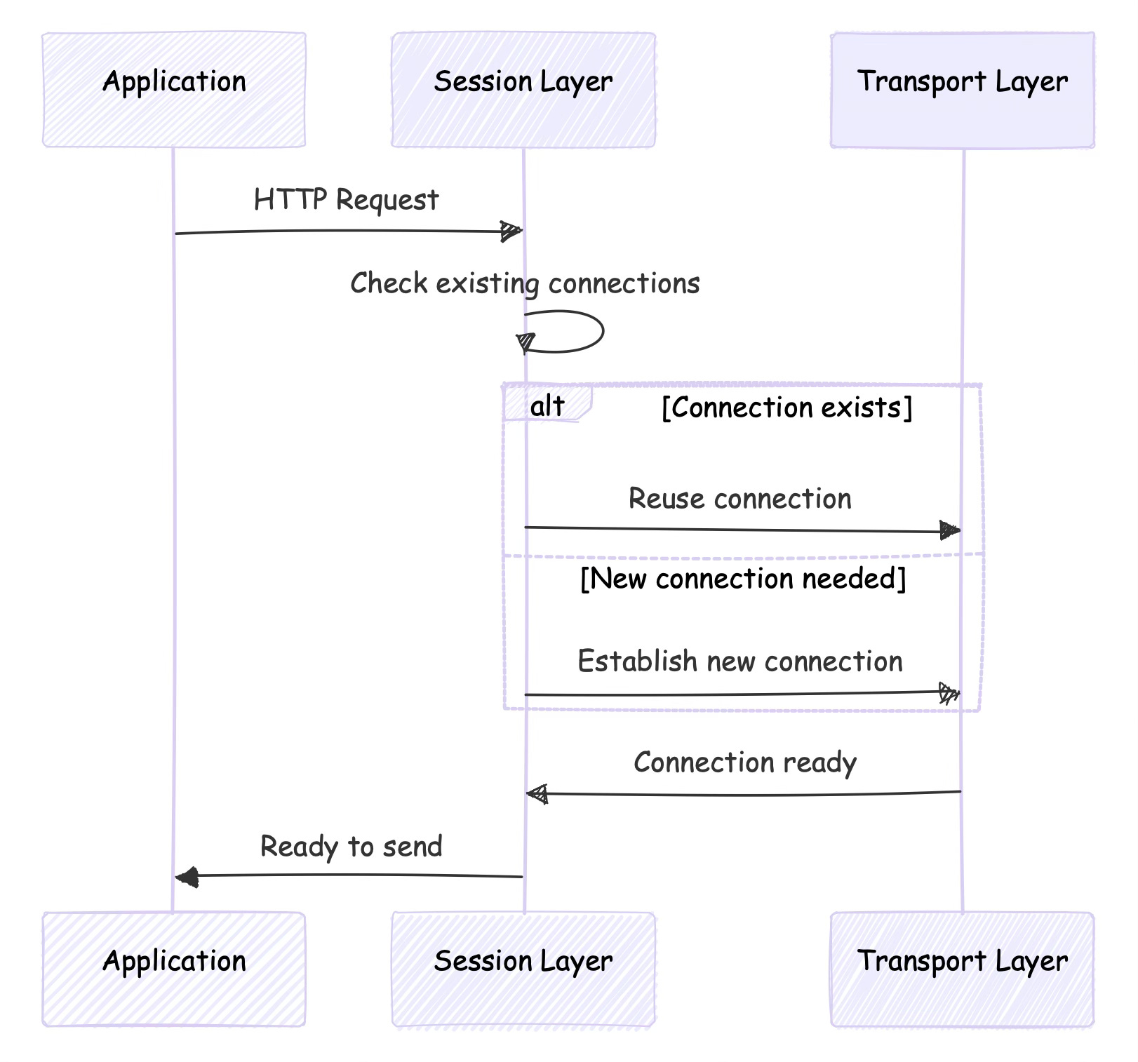
- Authentication tagLayer 5: Session Layer - Connection Management
In modern HTTP implementations, this layer manages:
Connection Persistence:
HTTP/1.1 keep-alive connections
Connection pooling for multiple requests
Session state management
HTTP/2 Specific Features:
Stream multiplexing within a single TCP connection
Header compression (HPACK)
Server push capabilities
Session Establishment Flow:
Layer 4: Transport Layer - Reliable Data Delivery
TCP takes center stage here, providing reliability over the unreliable IP network:
Segmentation:
For our small JSON payload (20 bytes), everything fits in one TCP segment
Maximum Segment Size (MSS) typically 1460 bytes on Ethernet
TCP Header Construction:
TCP Header (20 bytes minimum):
- Source Port: 54321 (ephemeral)
- Destination Port: 8080 (application server)
- Sequence Number: 12345678 (for ordering)
- Acknowledgment Number: 87654321
- Flags: ACK=1, PSH=1 (push data immediately)
- Window Size: 65535 (flow control)
- Checksum: 0x1234 (error detection)
- Urgent Pointer: 0 (not used)
Connection State Management:
If no existing connection: Three-way handshake (SYN → SYN-ACK → ACK)
Congestion control algorithms (Cubic, BBR)
Flow control via sliding window protocol
Reliability Mechanisms:
Sequence numbers for ordering
Acknowledgments for confirming receipt
Retransmission timers for lost packets
Duplicate detection
Layer 3: Network Layer - Routing and Addressing
The IP layer handles logical addressing and routing:
IPv4 Header Construction:
IPv4 Header (20 bytes minimum):
- Version: 4
- Header Length: 5 (20 bytes)
- Type of Service: 0x00 (best effort)
- Total Length: 60 (IP header + TCP header + data)
- Identification: 0x1234 (for fragmentation)
- Flags: Don't Fragment (DF=1)
- Fragment Offset: 0
- Time to Live: 64
- Protocol: 6 (TCP)
- Header Checksum: 0x5678
- Source IP: 192.168.1.10 (Backend A)
- Destination IP: 192.168.1.20 (Backend B)
Routing Decision Process:
Check if destination is on local subnet (subnet mask comparison)
If local: Use ARP to find MAC address
If remote: Send to default gateway
Routing table lookup for best path
Fragmentation Handling:
If packet size > MTU (1500 bytes for Ethernet): Fragment
Each fragment gets same IP ID, different offsets
Reassembly at destination
Layer 2: Data Link Layer - Local Network Delivery
The Ethernet layer handles physical addressing and frame formatting:
Ethernet Frame Structure:
Ethernet Frame (64-1518 bytes):
- Preamble: 7 bytes (synchronization)
- Start Frame Delimiter: 1 byte
- Destination MAC: 6 bytes (Backend B's MAC)
- Source MAC: 6 bytes (Backend A's MAC)
- EtherType: 2 bytes (0x0800 for IPv4)
- Payload: 46-1500 bytes (IP packet)
- Frame Check Sequence: 4 bytes (CRC-32)
MAC Address Resolution:
ARP request if MAC unknown: "Who has 192.168.1.20?"
ARP reply: "192.168.1.20 is at 00:1B:44:11:3A:B7"
MAC addresses cached for future use
Error Detection:
CRC-32 checksum calculation
Frame validation at receiver
Collision detection in shared media
Layer 1: Physical Layer - Bit Transmission
The lowest layer converts frames to electrical/optical signals:
Signal Encoding:
Manchester encoding for copper Ethernet
NRZ (Non-Return-to-Zero) for fiber optic
Bit timing at 1 Gbps (1 nanosecond per bit)
Physical Medium Characteristics:
Copper: Cat 6 cable, 100 meters max
Fiber: Single-mode for long distances
Signal attenuation and regeneration
Transmission Process:

Network Transit: The Journey Between Backends
Switch Processing
Ethernet switches operate at Layer 2:
MAC address table lookup
Frame forwarding to appropriate port
No modification of frame contents
Store-and-forward vs. cut-through switching
Router Processing
Routers operate at Layer 3:
IP header examination
Routing table lookup
TTL decrement
Frame re-encapsulation for next hop
Layer-by-Layer Breakdown: The Upward Journey (Backend B)
Layer 1: Physical Layer - Signal Reception
Backend B's network interface receives the electrical/optical signals:
Signal detection and amplification
Clock recovery for bit timing
Bit stream reconstruction
Frame boundary detection
Layer 2: Data Link Layer - Frame Validation
The Ethernet controller processes the incoming frame:
Preamble detection and synchronization
Frame Check Sequence validation
MAC address filtering (accept if matches or broadcast)
Frame length validation
Error Handling:
CRC mismatch: Frame discarded
Runt frames (< 64 bytes): Discarded
Giant frames (> 1518 bytes): Discarded
Layer 3: Network Layer - Packet Processing
IP layer processing at Backend B:
IP header checksum validation
Destination IP address verification
Fragment reassembly (if needed)
TTL processing
Routing Decision:
If destination IP matches local interface: Accept
If not: Forward (if router) or discard
Layer 4: Transport Layer - Reliable Delivery
TCP processing reconstructs the original data stream:
Sequence number validation
Acknowledgment generation
Out-of-order packet buffering
Flow control window updates
Connection State Update:
Update connection state
Slide receive window
Trigger acknowledgment transmission
Layer 5: Session Layer - Session Management
Session layer coordinates the request-response cycle:
Associate with existing HTTP connection
Handle connection keep-alive
Manage request pipelining (HTTP/1.1)
Layer 6: Presentation Layer - Data Transformation
Reverse of the encoding process:
TLS decryption (if HTTPS)
Data decompression (if compressed)
Character set conversion
Format validation
TLS Decryption Process:
Verify MAC for integrity
Decrypt using session keys
Verify padding
Extract plaintext HTTP request
Layer 7: Application Layer - Business Logic
Finally, the HTTP request reaches the application:
HTTP header parsing
Content-Type validation
JSON deserialization
Business logic execution
Request Processing:
Input: {"message": "Mohit"}
Processing: Extract "Mohit", apply business logic
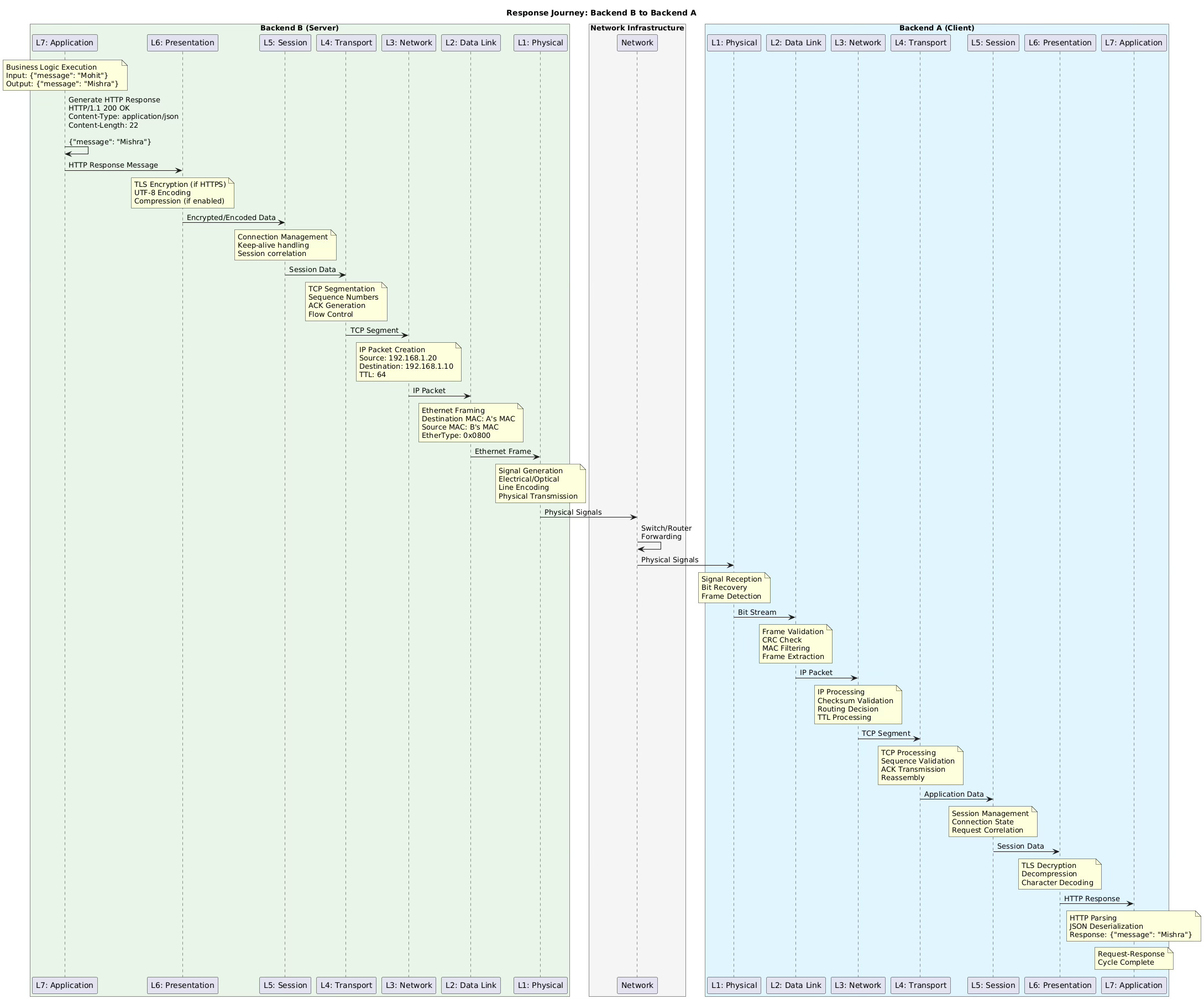
Output: {"message": "Mishra"}The Response Journey: Backend B to Backend A
The response follows the exact same layer-by-layer process in reverse:
Performance Considerations and Engineering Insights
Latency Breakdown
Application processing: 0.1-10ms
TCP/IP stack processing: 0.01-0.1ms
Network transmission: 0.1-100ms (depends on distance)
Switch/router processing: 0.001-0.01ms per hop
Bandwidth Utilization
Payload: 20 bytes JSON
Total overhead: ~54 bytes (Ethernet + IP + TCP + HTTP headers)
Efficiency: 20/74 = 27% for this small payload
Error Rates and Reliability
Bit Error Rate: 10^-12 for fiber, 10^-9 for copper
Frame Error Rate: 10^-8 to 10^-6
TCP provides 99.999% reliability through retransmission
Production Debugging Strategies
Network Monitoring Tools
tcpdumpfor packet capture at Layer 2-4wiresharkfor comprehensive protocol analysisss(socket statistics) for TCP connection statenetstatfor network interface statistics
Common Failure Points
Layer 1: Cable faults, signal degradation
Layer 2: MAC address conflicts, switch failures
Layer 3: Routing loops, TTL expiration
Layer 4: Port exhaustion, TCP timeouts
Layer 5: Connection pool exhaustion
Layer 6: TLS certificate issues, cipher mismatches
Layer 7: HTTP parsing errors, application timeouts
Performance Optimization Techniques
Connection Pooling: Reuse TCP connections
HTTP/2: Multiplexing, header compression
Compression: Reduce payload size
CDN: Reduce geographical latency
Load Balancing: Distribute traffic across multiple backends
Conclusion
This journey from {"message": "Mohit"} to {"message": "Mishra"} demonstrates the remarkable engineering that makes modern networking possible. Each layer adds value while maintaining clear separation of concerns. Understanding these layers is essential for:
Debugging network issues systematically
Optimizing application performance
Designing resilient distributed systems
Making informed architectural decisions
The OSI model, while sometimes criticized as overly theoretical, provides an invaluable framework for understanding and troubleshooting network communications in production environments.