
Layer 2 Network Operations: How Ethernet Frames and Smart Switches Power Gigabit Networks
Detailed Analysis of Switching and Bridging Mechanisms

After a packet completes its routing decision and determines its next hop destination, it enters the realm of Layer 2 networking. Here, logical IP addresses give way to physical MAC addresses, and the focus shifts from end-to-end paths to single-hop delivery across a local network segment. This transition marks a fundamental change in how network devices handle data, moving from routing based on network layer information to switching based on data link layer addresses.
The Layer 2 journey involves sophisticated mechanisms that have evolved tremendously since the early days of shared Ethernet. Modern switches are complex devices with specialized silicon, extensive memory buffers, and advanced protocols that ensure reliable, high-speed frame delivery. Understanding these mechanisms reveals how local networks achieve gigabit and even terabit speeds while maintaining microsecond latencies.
Ethernet Frame Construction
The transformation from IP packet to Ethernet frame represents a crucial encapsulation step in network communication. The operating system’s network stack takes the carefully crafted IP packet and wraps it in Ethernet headers that enable transmission across the physical network medium. This process involves precise formatting, address insertion, and length calculations that must conform to IEEE 802.3 standards.
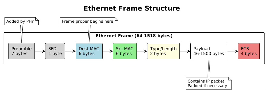
Ethernet frames begin with a preamble and start frame delimiter, though these are typically handled by the network interface card hardware rather than software. The frame header contains three essential fields: the destination MAC address (6 bytes), the source MAC address (6 bytes), and the EtherType or length field (2 bytes). The EtherType field indicates the encapsulated protocol, with 0x0800 representing IPv4 and 0x86DD representing IPv6.
# Capture and examine Ethernet frames
sudo tcpdump -i eth0 -e -nn -vv -X -c 1
# Output shows full Ethernet headers:
# 12:34:56.789012 00:11:22:33:44:55 > 00:aa:bb:cc:dd:ee, ethertype IPv4 (0x0800)
# length 98: 192.168.1.100.45678 > 93.184.216.34.80: TCP

# View interface MAC address
ip link show eth0
# 2: eth0: <BROADCAST,MULTICAST,UP,LOWER_UP> mtu 1500 qdisc fq_codel
#    link/ether 00:11:22:33:44:55 brd ff:ff:ff:ff:ff:ff
The frame payload carries the IP packet, which can range from 46 to 1500 bytes in standard Ethernet. If the IP packet is smaller than 46 bytes, the network stack adds padding bytes to meet the minimum frame size requirement. This minimum exists because of Ethernet’s collision detection mechanism, which requires frames to be on the wire long enough for collisions to be detected across the maximum cable length.
After the payload comes the Frame Check Sequence, a 32-bit CRC (Cyclic Redundancy Check) that allows receivers to detect transmission errors. The network interface card hardware typically calculates this checksum during transmission and verifies it during reception, offloading this computational task from the CPU.
MAC Header Addition
The MAC header addition process involves more than simply copying addresses into frame fields. The operating system must determine the correct source MAC address when multiple interfaces exist, handle special destination addresses for multicast and broadcast traffic, and ensure proper byte ordering for network transmission.
When constructing unicast frames, the destination MAC address comes from the ARP cache (for IPv4) or neighbor cache (for IPv6). The kernel looks up the next-hop IP address determined during routing and retrieves the corresponding MAC address. If no cache entry exists, the kernel queues the packet and initiates address resolution.
Broadcast frames use the special MAC address FF:FF:FF:FF:FF:FF, which all stations on the network segment must receive and process. Multicast frames use addresses where the least significant bit of the first byte is set to 1, indicating group addressing. IPv4 multicast addresses map to Ethernet multicast addresses using a defined algorithm, though this mapping is not unique, potentially causing unnecessary frame reception.
# Examine multicast MAC addresses
ip maddr show dev eth0
# 2:  eth0
#     link  01:00:5e:00:00:01  # All hosts multicast
#     link  33:33:00:00:00:01  # IPv6 all-nodes multicast
#     link  33:33:ff:11:22:33  # IPv6 solicited-node multicast

# Monitor frame construction in kernel
sudo perf trace -e net:net_dev_xmit
Virtual interfaces like VLANs, bridges, and bonds complicate MAC header addition. These interfaces might use their own MAC addresses or inherit addresses from physical interfaces. The kernel maintains a mapping between logical interfaces and their associated MAC addresses, updating frames appropriately as they traverse the virtual interface stack.
Frame Check Sequence (FCS) Calculation
The Frame Check Sequence provides error detection for Ethernet frames, using a 32-bit CRC polynomial standardized by IEEE. While network interface cards typically handle FCS calculation and verification in hardware, understanding the process illuminates how networks detect corruption during transmission.
The CRC-32 algorithm treats the frame as a large binary number and performs polynomial division using the generator polynomial x^32 + x^26 + x^23 + x^22 + x^16 + x^12 + x^11 + x^10 + x^8 + x^7 + x^5 + x^4 + x^2 + x + 1. The remainder of this division becomes the FCS value appended to the frame.
Modern network interfaces implement FCS calculation in dedicated hardware, achieving line-rate processing even at 100 Gigabit speeds. The hardware calculates the FCS as frame bytes stream through the transmit path, appending the final value without additional latency.
# Check FCS offload capabilities
ethtool -k eth0 | grep tx-checksumming
# tx-checksumming: on
#     tx-checksum-ipv4: on
#     tx-checksum-ipv6: on

# Monitor FCS errors
ethtool -S eth0 | grep fcs
# rx_fcs_errors: 0
# tx_fcs_errors: 0
MTU Considerations and Jumbo Frames
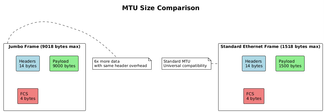
Maximum Transmission Unit (MTU) defines the largest frame size that can traverse a network segment without fragmentation. Standard Ethernet specifies an MTU of 1500 bytes for the payload, though this seemingly simple parameter has profound implications for network performance and application behavior.
The 1500-byte MTU originated from early Ethernet’s electrical characteristics and the need to balance efficiency with fairness in a shared medium. Larger frames improve efficiency by reducing header overhead, while smaller frames ensure timely medium access for all stations. Although modern switched networks eliminate the shared medium concern, the 1500-byte standard persists for compatibility.
Jumbo frames extend the MTU beyond 1500 bytes, typically to 9000 bytes, though no universal standard exists. These larger frames significantly improve throughput for bulk data transfers by reducing the per-packet processing overhead. A single 9000-byte jumbo frame can carry the same data as six standard frames, reducing CPU interrupts and processing cycles by a factor of six.
# Check current MTU setting
ip link show eth0 | grep mtu
# eth0: <BROADCAST,MULTICAST,UP,LOWER_UP> mtu 1500

# Configure jumbo frames
sudo ip link set dev eth0 mtu 9000

# Verify jumbo frame support in hardware
sudo ethtool -i eth0
# driver: e1000e
# version: 3.2.6-k
# firmware-version: 0.13-4

# Test path MTU to destination
ping -M do -s 8972 192.168.1.100
# -M do: Set Don’t Fragment bit
# -s 8972: 8972 bytes + 28 bytes (IP + ICMP headers) = 9000
MTU mismatches cause significant problems in networks. When a frame exceeds the next-hop’s MTU, the device must either fragment the packet (for IPv4 without DF bit) or drop it and send an ICMP “Packet Too Big” message. Path MTU Discovery attempts to determine the minimum MTU along a path, but ICMP filtering often breaks this mechanism, leading to mysterious connectivity issues.
Switch Operation Deep Dive
Modern Ethernet switches operate as high-speed, multiport bridges that make forwarding decisions based on MAC addresses. Unlike their hub predecessors that blindly repeated signals, switches examine each frame’s destination MAC address and forward it only to the appropriate port. This intelligence transforms Ethernet from a shared medium into a switched fabric with dedicated bandwidth per port.
The switch’s data plane handles the actual frame forwarding, implemented in specialized ASICs (Application-Specific Integrated Circuits) that process frames at wire speed. These chips contain Content Addressable Memory (CAM) tables that enable hardware-based MAC address lookups in constant time, regardless of table size. A modern data center switch can forward billions of frames per second with latencies measured in nanoseconds.
The control plane manages the switch’s learning process, protocol operations, and table maintenance. Running on the switch’s CPU, the control plane handles Spanning Tree Protocol calculations, VLAN configurations, and management interface operations. While the data plane forwards frames independently, the control plane provides the intelligence that adapts to network changes.
Switch architectures vary based on design requirements and cost constraints. Store-and-forward switches receive entire frames before forwarding, allowing complete error checking but adding latency. Cut-through switches begin forwarding after reading just the destination address, minimizing latency but potentially propagating corrupted frames. Fragment-free switching represents a compromise, checking the first 64 bytes to catch most collisions before forwarding.
# On a Linux bridge (software switch) examine switching behavior
# Create a bridge
sudo ip link add br0 type bridge
sudo ip link set dev eth0 master br0
sudo ip link set dev eth1 master br0
sudo ip link set dev br0 up

# View bridge forwarding database
bridge fdb show br br0
# 00:11:22:33:44:55 dev eth0 master br0 permanent
# 00:aa:bb:cc:dd:ee dev eth1 master br0 permanent
# 00:12:34:56:78:90 dev eth0 vlan 1 master br0

# Monitor learning process
bridge monitor fdb
MAC Address Table Learning
Switches learn MAC addresses dynamically by observing source addresses in received frames. When a frame arrives on a port, the switch extracts the source MAC address and creates an entry mapping that address to the receiving port. This learning process builds the forwarding database without manual configuration, adapting automatically as devices connect, disconnect, or move between ports.
The learning process operates continuously, with each received frame potentially updating the MAC address table. If a MAC address appears on a different port than previously recorded, the switch updates its table, enabling mobility as devices move between network segments. This dynamic learning makes switches plug-and-play devices that require minimal configuration.
MAC address tables have finite capacity, typically ranging from thousands of entries in access switches to millions in core switches. When the table fills, switches must either stop learning new addresses or age out existing entries. Most switches implement a Least Recently Used (LRU) algorithm, evicting the oldest unused entries to make room for new addresses.
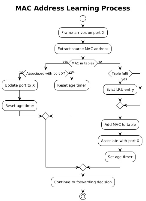
Aging mechanisms prevent stale entries from persisting indefinitely. Each MAC address entry has an associated timer, typically set to 300 seconds by default. When the switch sees traffic from a MAC address, it resets the timer. If the timer expires without seeing traffic, the switch removes the entry, forcing re-learning if the device becomes active again.
Forwarding Decision Process
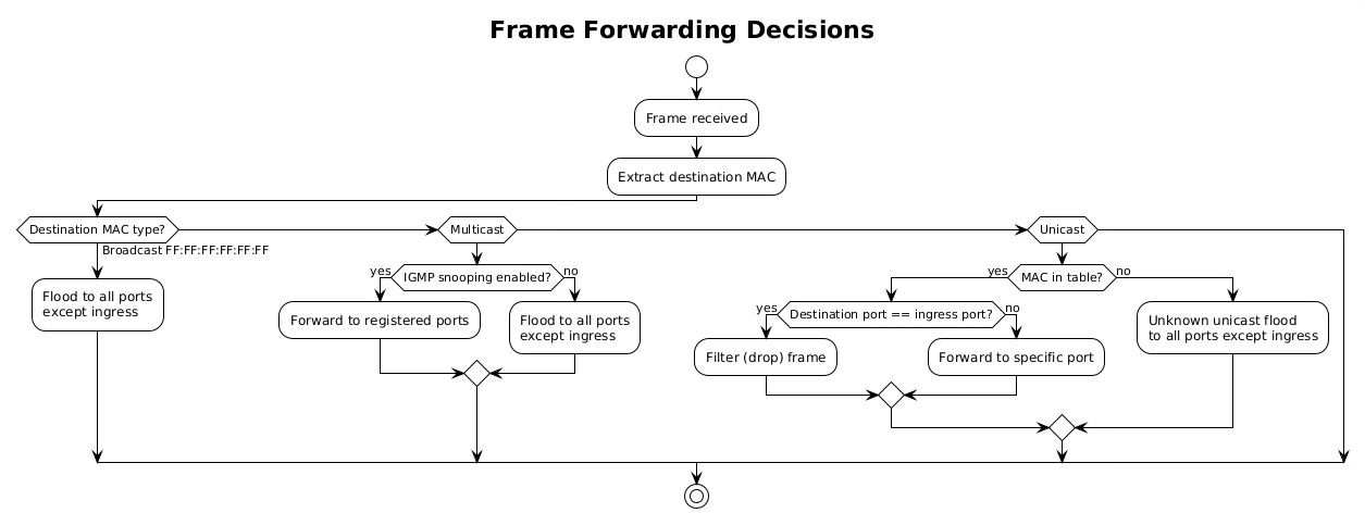
Once a switch learns MAC addresses, it uses this knowledge to make intelligent forwarding decisions. The process begins when a frame arrives on an ingress port. The switch examines the destination MAC address and performs a lookup in its MAC address table. Three outcomes are possible: the address is known and associated with a specific port, the address is unknown, or the address is a broadcast/multicast requiring special handling.
For known unicast addresses, the switch forwards the frame only to the port associated with the destination MAC. If that port is the same as the ingress port, the switch filters (drops) the frame, as the destination must already be on the same network segment. This filtering prevents unnecessary traffic and is particularly important in preventing loops.
Unknown unicast frames trigger flooding behavior. The switch forwards the frame to all ports except the ingress port, essentially treating it like a broadcast. This ensures delivery even when the destination hasn’t been learned yet. The destination’s reply will trigger learning, allowing subsequent frames to be forwarded specifically.
# Examine forwarding decisions on Linux bridge
# Show forwarding database with port associations
bridge -d fdb show
# 00:11:22:33:44:55 dev eth0 vlan 1 master br0 permanent
# 00:aa:bb:cc:dd:ee dev eth1 vlan 1 offload master br0
# 00:12:34:56:78:90 dev eth0 vlan 1 extern_learn master br0

# Check bridge port states
bridge -d link show
# 2: eth0: <BROADCAST,MULTICAST,UP,LOWER_UP> mtu 1500 master br0
#     state forwarding priority 32 cost 4
# 3: eth1: <BROADCAST,MULTICAST,UP,LOWER_UP> mtu 1500 master br0
#     state forwarding priority 32 cost 4
Broadcast, Multicast, and Unicast Handling
Switches handle different traffic types with distinct forwarding behaviors. Broadcast frames, destined to FF:FF:FF:FF:FF:FF, must reach every device in the broadcast domain. The switch floods these frames to all ports except the ingress port, ensuring complete coverage. Broadcast traffic includes ARP requests, DHCP discoveries, and certain routing protocols.
Multicast traffic presents unique challenges. Without special handling, switches treat multicast like broadcast, flooding it throughout the network. This wastes bandwidth when only specific hosts want the multicast stream. IGMP snooping solves this by monitoring Internet Group Management Protocol messages to learn which ports have interested receivers, forwarding multicast only where needed.
Unicast traffic receives the most optimized treatment. The switch forwards unicast frames to a single port, providing dedicated bandwidth between communicating devices. This creates multiple collision domains, allowing simultaneous conversations without interference. In a fully switched network with non-blocking architecture, every port pair can communicate at full wire speed simultaneously.
VLAN Processing
Virtual Local Area Networks (VLANs) partition a physical switch into multiple logical switches, each with its own broadcast domain. VLANs provide network segmentation without requiring separate physical infrastructure, enabling flexible network designs that can span multiple switches while maintaining isolation between different traffic types.
VLAN processing begins at frame ingress. The switch examines whether the frame carries an 802.1Q VLAN tag, a 4-byte header inserted between the source MAC address and EtherType fields. This tag contains a 12-bit VLAN identifier (VID) allowing up to 4094 distinct VLANs (VLAN 0 and 4095 are reserved).
Ports operate in different VLAN modes. Access ports connect to end devices and belong to a single VLAN. Frames entering access ports are untagged; the switch adds the port’s VLAN tag internally. Trunk ports connect switches and carry multiple VLANs, maintaining tags to preserve VLAN membership across switches.
# Configure VLANs on Linux bridge
sudo ip link add link eth0 name eth0.100 type vlan id 100
sudo ip link add link eth0 name eth0.200 type vlan id 200

# Add VLAN interfaces to bridge
sudo ip link set dev eth0.100 master br0
sudo ip link set dev eth0.200 master br0

# View VLAN configuration
bridge vlan show
# port    vlan ids
# eth0     1 PVID Egress Untagged
#          100
#          200
# br0      1 PVID Egress Untagged

# Monitor VLAN tagged traffic
sudo tcpdump -i eth0 -e vlan
VLAN Tag Insertion/Removal
VLAN tag manipulation occurs at port boundaries based on port configuration. When a frame enters an access port, the switch inserts the port’s configured VLAN ID into the frame’s internal representation. This internal tag travels with the frame through the switch fabric but doesn’t necessarily appear in the transmitted frame.
Tag insertion involves shifting the frame contents to create space for the 802.1Q header. The switch inserts the Tag Protocol Identifier (TPID) of 0x8100, followed by the Priority Code Point (3 bits), Drop Eligible Indicator (1 bit), and VLAN ID (12 bits). This insertion increases the frame size by 4 bytes, which is why VLAN-aware networks often configure a slightly higher MTU.
Tag removal occurs when frames exit access ports. The switch strips the 802.1Q header, restoring the original frame format expected by end devices. This transparent operation allows VLAN-unaware devices to participate in VLANs without modification.
Inter-VLAN Routing Decisions
VLANs create separate broadcast domains that cannot communicate without routing. Inter-VLAN routing requires a Layer 3 device, either a router or a Layer 3 switch, to forward packets between VLANs. This routing can occur through different methods, each with distinct performance and scalability characteristics.
Router-on-a-stick configurations use a single physical connection between switch and router, with subinterfaces handling different VLANs. The switch sends VLAN-tagged frames to the router, which removes the tag, performs routing, and sends the packet back with the destination VLAN tag. This approach works but creates a bottleneck at the router interface.
Layer 3 switches integrate routing into the switch hardware, performing inter-VLAN routing at wire speed. These switches maintain routing tables like traditional routers but implement forwarding in ASICs rather than software. Switched Virtual Interfaces (SVIs) provide IP addresses for each VLAN, enabling direct routing without external devices.
# Configure inter-VLAN routing on Linux
# Create VLAN interfaces with IP addresses
sudo ip addr add 192.168.100.1/24 dev eth0.100
sudo ip addr add 192.168.200.1/24 dev eth0.200

# Enable routing
sudo sysctl -w net.ipv4.ip_forward=1

# View routing between VLANs
ip route show
# 192.168.100.0/24 dev eth0.100 proto kernel scope link
# 192.168.200.0/24 dev eth0.200 proto kernel scope link
Trunk Port Operations
Trunk ports carry multiple VLANs between switches, preserving VLAN membership as traffic traverses the network infrastructure. These ports must handle both tagged and untagged frames, making decisions about which VLANs to allow and how to handle untagged traffic.
The 802.1Q standard defines trunk port behavior. Tagged frames pass through with their VLAN tags intact, allowing VLAN membership to persist across switches. Untagged frames receive the port’s native VLAN tag, providing backward compatibility with non-VLAN-aware devices. The native VLAN concept can create security vulnerabilities if not properly configured, as it allows VLAN hopping attacks.
Trunk ports maintain allowed VLAN lists that filter traffic. Administrators configure which VLANs can traverse each trunk, reducing unnecessary broadcast propagation and improving security. VLAN pruning dynamically adjusts these lists based on actual VLAN membership, further optimizing bandwidth usage.
Spanning Tree Protocol Impact
The Spanning Tree Protocol (STP) prevents loops in redundant Layer 2 networks by blocking redundant paths. While redundancy improves reliability, Ethernet’s learning and flooding mechanisms would cause broadcast storms without loop prevention. STP creates a loop-free logical topology while maintaining the physical redundancy for failover.
STP operation begins with bridge election. Switches exchange Bridge Protocol Data Units (BPDUs) containing bridge IDs and path costs. The switch with the lowest bridge ID becomes the root bridge, serving as the logical center of the spanning tree. All other switches calculate their shortest path to the root, blocking redundant paths to prevent loops.
Port states control frame forwarding during STP convergence. Ports transition through multiple states: blocking (no forwarding), listening (processing BPDUs), learning (building MAC table), and forwarding (normal operation). This progression prevents temporary loops during topology changes but can take 30-50 seconds with standard STP.
# Configure STP on Linux bridge
sudo ip link set dev br0 type bridge stp_state 1

# View STP status
bridge -d link show
# 2: eth0: <BROADCAST,MULTICAST,UP,LOWER_UP> state forwarding
#     priority 32 cost 4 hairpin off guard off root_block off
#     fastleave off learning on flood on port_id 0x8001 port_no 0x1

# Monitor BPDU exchanges
sudo tcpdump -i eth0 -s0 -c 10 ‘ether dst 01:80:c2:00:00:00’
Port States and Forwarding Decisions
STP port states directly influence switching behavior. Blocking ports drop all user frames, preventing loops but maintaining BPDU reception to detect topology changes. Listening ports process BPDUs and participate in topology calculations but don’t forward user traffic or learn MAC addresses.
Learning ports begin MAC address table population but still don’t forward frames. This state allows the switch to build its forwarding database before entering production, reducing unknown unicast flooding when forwarding begins. The learning state typically lasts 15 seconds, giving adequate time for address discovery.
Forwarding ports operate normally, learning addresses and forwarding frames according to the MAC address table. Root ports (facing toward the root bridge) and designated ports (facing away from the root) enter forwarding state, while alternate and backup ports remain blocked to prevent loops.
Loop Prevention Mechanisms
Beyond basic STP, modern networks employ additional loop prevention mechanisms. BPDU Guard immediately disables ports that receive BPDUs, protecting against accidental switch connections on access ports. Root Guard prevents downstream switches from becoming the root bridge, maintaining topology control.
Loop Guard detects unidirectional link failures that could cause loops. When a port stops receiving BPDUs, Loop Guard places it in loop-inconsistent state rather than transitioning to forwarding. This prevents loops when link failures affect only one direction of transmission.
Storm control provides rate limiting for broadcast, multicast, and unknown unicast traffic. When traffic exceeds configured thresholds, the switch can drop excess frames or disable the port entirely. This mechanism contains broadcast storms whether caused by loops, malfunctioning NICs, or application misbehavior.
Link Aggregation (LACP) Considerations
Link Aggregation Control Protocol (LACP) bundles multiple physical links into a single logical interface, providing increased bandwidth and redundancy. This IEEE 802.3ad standard enables switches to negotiate aggregation automatically, detecting and configuring bundled links without manual intervention.
LACP operates by exchanging Link Aggregation Control Protocol Data Units (LACPDUs) between partners. These messages contain system priorities, port priorities, and operational keys that identify which ports can form an aggregation. Partners must agree on aggregation parameters before activating the bundle.
Load distribution across aggregated links uses various algorithms. Simple implementations use source/destination MAC address hashing, while advanced switches consider IP addresses, TCP/UDP ports, or even application data. The hashing ensures that frames from the same flow follow the same physical link, preserving order.
# Configure link aggregation on Linux
sudo ip link add bond0 type bond mode 802.3ad
sudo ip link set eth0 master bond0
sudo ip link set eth1 master bond0
sudo ip link set bond0 up

# View aggregation status
cat /proc/net/bonding/bond0
# Bonding Mode: IEEE 802.3ad Dynamic link aggregation
# Transmit Hash Policy: layer2+3 (2)
# MII Status: up
# Active Aggregator Info:
#     Aggregator ID: 1
#     Number of ports: 2

# Monitor LACPDU exchange
sudo tcpdump -i eth0 -e ether proto 0x8809
Buffer Management in Switches
Switch buffers absorb traffic bursts and handle speed mismatches between ports. When frames arrive faster than they can be transmitted, buffers queue them temporarily. Buffer architecture significantly impacts switch performance, especially under congestion.
Shared buffer architectures pool memory across all ports, allowing any port to use available buffer space. This flexibility handles asymmetric traffic patterns efficiently but requires complex arbitration to prevent single ports from monopolizing buffers. Port-based buffers dedicate memory to each port, providing isolation but potentially wasting memory when traffic patterns are uneven.
Buffer allocation strategies determine how switches handle congestion. Tail drop simply discards frames when buffers fill, leading to TCP synchronization problems. Random Early Detection (RED) probabilistically drops frames before buffers fill completely, signaling congestion earlier and more fairly. Weighted RED (WRED) extends this with different drop probabilities for different traffic classes.
Output queue scheduling determines frame transmission order when multiple frames compete for the same egress port. Strict priority scheduling always serves higher priority queues first, potentially starving lower priorities. Weighted Fair Queuing (WFQ) allocates bandwidth proportionally, ensuring all classes receive service. Deficit Round Robin (DRR) provides fair scheduling with lower computational complexity than WFQ.
Collision Domains and Broadcast Domains
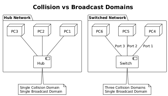
Understanding collision and broadcast domains reveals fundamental differences between hubs, switches, and routers. Collision domains define where frame collisions can occur, while broadcast domains define broadcast frame propagation boundaries.
Hubs create single collision domains where all connected devices compete for medium access. Simultaneous transmissions cause collisions, requiring CSMA/CD (Carrier Sense Multiple Access with Collision Detection) mechanisms. As more devices join a hub, collision probability increases, degrading performance dramatically.
Switches eliminate collision domains by providing dedicated bandwidth per port. Each switch port creates its own collision domain, allowing full-duplex communication without collisions. This architectural change enabled Ethernet to scale from 10 Mbps shared networks to today’s 400 Gbps switched fabrics.
Broadcast domains encompass all devices that receive broadcast frames. Switches forward broadcasts to all ports, creating single broadcast domains per VLAN. Large broadcast domains suffer from excessive broadcast traffic, consuming bandwidth and processing resources. VLANs segment broadcast domains, improving scalability and security.
Switch Fabric Architectures
The switch fabric represents the internal architecture that moves frames between ports. Fabric design determines the switch’s aggregate throughput, latency characteristics, and ability to handle concurrent flows. Three primary architectures dominate modern switches: shared memory, shared bus, and crossbar.
Shared memory architectures use a central memory pool accessed by all ports. Ingress ports write frames to memory while egress ports read them. A central controller manages memory allocation and scheduling. This design offers flexibility and efficient multicast handling but requires extremely fast memory to support high port densities.
Shared bus architectures connect all ports to a common backplane bus. Only one port can transmit on the bus at a time, creating a potential bottleneck. Time Division Multiplexing (TDM) allocates bus time slots to ports, guaranteeing bandwidth but limiting aggregate throughput. Modern switches rarely use pure shared bus designs due to scalability limitations.
Crossbar architectures provide dedicated paths between every input/output port pair. Multiple conversations can occur simultaneously without interference, limited only by port speeds rather than fabric capacity. Crossbars scale well but require N² connection points for N ports, increasing cost and complexity. Multi-stage crossbars reduce complexity while maintaining non-blocking performance.
# Examine software switch performance metrics
# Monitor switching performance
sar -n DEV 1 5
# Average:     IFACE   rxpck/s   txpck/s    rxkB/s    txkB/s
# Average:     eth0    15234.20  14892.80  22851.30  21338.70
# Average:     br0     15234.20  14892.80  22851.30  21338.70

# Check for switching bottlenecks
sudo ethtool -S eth0 | grep -E ‘drop|error|overflow’
# rx_dropped: 0
# tx_dropped: 0
# rx_errors: 0
# tx_errors: 0
# rx_fifo_overflow: 0
Advanced fabrics implement Virtual Output Queuing (VOQ) to prevent head-of-line blocking. Instead of queuing frames at ingress ports, VOQ maintains separate queues for each egress port at every ingress. This prevents a congested egress port from blocking frames destined to other ports, improving overall throughput under congestion.
Modern data center switches push fabric innovations further with cell-based switching, similar to ATM. Frames are segmented into fixed-size cells that traverse the fabric independently, reassembling at egress. This approach reduces latency variation and improves buffer utilization, critical for high-frequency trading and real-time applications.
The evolution from shared media Ethernet to today’s sophisticated switching fabrics represents one of networking’s greatest achievements. These Layer 2 mechanisms, operating invisibly beneath IP routing, provide the high-speed, reliable foundation that enables modern networked applications. Understanding their operation reveals the careful engineering required to move billions of frames per second while maintaining microsecond latencies and preventing network loops.
🔥