
Why Packet Data Not Need a Trailer/Footer While a Frame Needs It
Exploring the Clever Design Behind Frames Needing Trailers and Packets Going Without

Have you ever wondered why network frames require trailers, but packets don't? This seemingly small detail reveals much about how network protocols are designed and the different responsibilities at each networking layer.
I remember being confused by this distinction during my first computer networks course - it seemed arbitrary until I understood the underlying reasons.
Understanding the Layered Network Model
Before diving into the specifics of headers and trailers, we need to establish a common understanding of where packets and frames fit in the networking stack.
Network communications follow a layered model, with two predominant reference frameworks:
ISO OSI Model: A theoretical seven-layer model
TCP/IP Model: A practical four or five-layer model that powers the Internet
In both models, packets belong to the Network layer (Layer 3 in OSI), while frames operate at the Data Link layer (Layer 2). Each layer encapsulates data from the layer above, adding its own control information.

When data travels down the stack:
Each layer adds its own header to the front of the data
Typically only the Data Link layer adds a trailer to the end
This pattern isn't coincidental - it reflects fundamental differences in how these protocols function and the problems they solve.
Structure of Protocol Data Units (PDUs)
Frame Structure (Data Link Layer)
A typical Ethernet frame looks like this:

The Frame Check Sequence (FCS) in the trailer contains a Cyclic Redundancy Check (CRC) calculated over the entire frame (excluding the preamble and start frame delimiter). It's a crucial component used for detecting transmission errors.
Packet Structure (Network Layer)
An IPv4 packet, by contrast, has this structure:
+----------------+----------------+----------------+----------------+
| Version + IHL  | ToS / DSCP     | Total Length   | Identification |
| (1 byte)       | (1 byte)       | (2 bytes)      | (2 bytes)      |
+----------------+----------------+----------------+----------------+
| Flags +        | TTL            | Protocol       | Header         |
| Fragment       | (1 byte)       | (1 byte)       | Checksum       |
| Offset         |                |                | (2 bytes)      |
| (2 bytes)      |                |                |                |
+----------------+----------------+----------------+----------------+
| Source IP Address (4 bytes)                                       |
+-------------------------------------------------------------------+
| Destination IP Address (4 bytes)                                  |
+-------------------------------------------------------------------+
| Options (if any)                                                  |
+-------------------------------------------------------------------+
| Data / Payload                                                    |
+-------------------------------------------------------------------+
Notice the absence of any trailer. All control information is contained in the header, including a Total Length field and Header Checksum.
Why Frames Need Trailers
Frames need trailers for several critical reasons that relate directly to the data link layer's function within the network stack.
Physical Layer Delimitation
The data link layer interfaces directly with the physical layer, which fundamentally deals with continuous streams of bits. A key problem for the data link layer is determining where one frame ends and another begins.
Early networking technologies used special bit patterns as delimiters. Ethernet originally used a technique called Manchester encoding that included specific patterns to indicate the start and end of transmission. Modern Ethernet starts with a preamble sequence (10101010...) followed by a start frame delimiter (10101011), but relies on the length field and counting bytes to know where the frame ends.
For technologies that don't have a predetermined frame size or a length field in the header, the trailer becomes essential - it contains patterns that signal "this is the end of the frame." HDLC (High-Level Data Link Control) is a good example of a protocol that uses flag sequences (01111110) to mark both the beginning and end of frames.
I once debugged a peculiar network issue where frames were getting corrupted because the receiving equipment was configured for a different framing standard. The equipment couldn't recognize the ending delimiters, causing it to merge multiple frames together. Without proper frame delimitation, reliable communication is impossible.
Error Detection Is Critical at the Link Layer
The data link layer is where the most errors occur in transmission because it's closest to the physical medium (cables, radio waves, etc.) where electrical interference, signal attenuation, and other issues can corrupt bits.
The trailer typically contains a Cyclic Redundancy Check (CRC) value calculated over the entire frame. This value allows the receiver to verify the integrity of the received frame by recalculating the CRC and comparing it with the received value.
The CRC calculation is specifically designed to detect:
Single bit errors
Double bit errors
Odd numbers of bit errors
Burst errors (up to a certain length)
Placing this error detection code at the end of the frame is intentional - it allows the calculation to happen as the frame is being transmitted, byte by byte, without requiring the entire frame to be buffered first.
Let's look at a simplified assembly example of how a network card might compute a CRC. This is a basic CRC-32 calculation loop for x86:
; Calculate CRC-32 for Ethernet frame
; Input: ESI = pointer to frame data (without FCS)
;        ECX = length in bytes
; Output: EAX = calculated CRC-32 value

    mov eax, 0xFFFFFFFF    ; Initialize CRC to all 1's
crc_loop:
    mov dl, [esi]          ; Get next byte from frame
    inc esi                ; Point to next byte
    xor al, dl             ; XOR with least significant byte of CRC

    ; Shift and XOR with polynomial for 8 bits
    mov ebx, 8             ; Process 8 bits
bit_loop:
    shr eax, 1             ; Shift right by 1 bit
    jnc no_xor             ; If no carry, skip XOR
    xor eax, 0xEDB88320    ; XOR with reversed CRC-32 polynomial
no_xor:
    dec ebx                ; Decrement bit counter
    jnz bit_loop           ; Loop until all 8 bits are processed

    dec ecx                ; Decrement byte counter
    jnz crc_loop           ; Loop until all bytes are processed

    not eax                ; Final inversion
    ; EAX now contains the CRC-32 value for the trailer
The network card processes the frame serially as bits arrive. Once it reaches the end of the data portion, it has the completed CRC calculation ready to compare with the received trailer. This streaming calculation method is extremely efficient for hardware implementation.
Hardware Efficiency Considerations
Networking hardware is designed for speed and efficiency. When receiving a frame, the network interface card (NIC) calculates the CRC as the bits arrive, then compares it with the trailer. This approach allows immediate processing without needing to buffer the entire frame first.
The placement of the CRC in a trailer rather than a header is therefore not arbitrary - it's a deliberate design choice that enables on-the-fly error detection with minimal hardware resources.
Why Packets Don't Need Trailers
Now let's examine why packets at the network layer don't include trailers. This design choice reflects different requirements and assumptions at this higher layer.
Length Information is Already Present
Packets don't need special delimiters because they include explicit length information in their headers:
In IPv4, the Total Length field (16 bits) specifies the entire packet length including header and data
In IPv6, the Payload Length field (16 bits) specifies the payload size (the header is fixed at 40 bytes)
This means that once a network device starts processing an IP packet, it immediately knows exactly how many bytes to expect. There's no need for an end-marker trailer.
Protected by Lower Layers
Packets operate at a higher layer of abstraction than frames. A key principle of layered networking is that each layer can rely on the services provided by lower layers. In this case, IP packets rely on the data link layer (frames) to:
Correctly delimit the beginning and end of transmissions
Detect and potentially correct transmission errors
When an IP packet is transmitted over Ethernet, the entire packet becomes the payload of an Ethernet frame, and is therefore protected by the frame's CRC in the trailer. If the frame's CRC check fails, the frame (and the contained packet) is typically discarded before it even reaches IP processing.
Eliminating redundant error detection improves overall efficiency - why check for errors twice?
Here's how the encapsulation looks:
+------------------------+
| IP Header              |
+------------------------+
| Transport Layer Data   |
+------------------------+
            ↓
+-----------+------------------------+-----------+
| Ethernet  | IP Packet              | Ethernet  |
| Header    | (Header + Data)        | FCS       |
+-----------+------------------------+-----------+
I once worked on a networking stack for an embedded device where we accidentally implemented redundant CRC checks at multiple layers. The performance impact was measurable - we were essentially doing the same work twice with no additional benefit.
End-to-End Principle
Networking design follows what's called the "end-to-end principle," which suggests that certain functions (like error recovery) should be implemented completely at the end points, rather than in intermediate systems.
While the data link layer handles hop-by-hop transmission between directly connected nodes, the transport layer (TCP) provides end-to-end reliability through mechanisms like checksums and acknowledgments. The network layer (IP) sits in between and deliberately provides a "best-effort" service without reliable delivery guarantees.
Since data link trailers are stripped off at each hop, they cannot provide end-to-end protection. Higher layers use their own error detection mechanisms when needed:
IP includes a header checksum that protects only the header (not the payload)
TCP/UDP include checksums that cover the header and payload
Application protocols may implement their own error detection and correction
Different Error Recovery Strategies
At the data link layer, frames with errors are typically discarded and retransmitted because:
Errors are relatively common at this layer
Retransmission can happen quickly between adjacent nodes
There's usually a direct, dedicated link between nodes
At the network layer, error recovery is handled differently:
Packets may traverse many networks with varying reliability
End-to-end retransmission is more complex and slower
Some applications can tolerate occasional errors or losses
These different strategies affect protocol design. The data link layer focuses on immediate error detection (using trailers with CRCs), while IP provides minimal error checking and leaves comprehensive error recovery to TCP or applications.
Low-Level Mechanics: A Closer Look
Framing in the Wild: HDLC Example
To better understand frame delimitation, let's look at HDLC (High-Level Data Link Control), which uses a flag byte (01111110) to mark both the beginning and end of a frame:
+--------+--------+------...------+--------+--------+
| Flag   | Header | Information   | FCS    | Flag   |
| 7E hex |        |               |        | 7E hex |
+--------+--------+------...------+--------+--------+
But what happens if the flag pattern (01111110) naturally occurs in the data? HDLC solves this with "bit stuffing":
After five consecutive 1s in the data, the sender automatically inserts a 0
The receiver automatically removes any 0 that follows five consecutive 1s
This ensures the flag pattern never appears within the frame data, making it an unambiguous delimiter.
Here's a simplified bit stuffing example:
Original data:
110111110101After bit stuffing:
110111100101(0 inserted after five 1s)
This mechanism guarantees that the flag pattern (01111110) only appears at the intended frame boundaries, solving the delimitation problem elegantly.
CRC Calculation: The Mathematics
The CRC in a frame trailer involves fascinating mathematics that's worth understanding. A CRC treats the entire message as a binary polynomial and performs polynomial division by a predetermined generator polynomial.
For Ethernet's CRC-32, the generator polynomial is: x³² + x²⁶ + x²³ + x²² + x¹⁶ + x¹² + x¹¹ + x¹⁰ + x⁸ + x⁷ + x⁵ + x⁴ + x² + x + 1
In practice, hardware implementations use shift registers and XOR operations rather than actual polynomial division. The result is a 32-bit value that's extremely sensitive to changes in the message - even a one-bit change typically produces a completely different CRC.
Here's a more practical x86 assembly implementation of CRC-32 using a pre-computed lookup table for efficiency:
; Calculate CRC-32 using table lookup method
; ESI = pointer to data, ECX = length, EDI = pointer to CRC table
; Returns CRC-32 in EAX

    mov eax, 0FFFFFFFFh    ; Initialize CRC to all 1's
crc_loop:
    movzx ebx, byte ptr [esi]  ; Get next byte from data
    inc esi                    ; Move to next byte
    xor bl, al                 ; XOR with least significant byte of CRC
    shr eax, 8                 ; Shift CRC right by 8 bits
    mov edx, [edi + ebx*4]     ; Lookup pre-computed value
    xor eax, edx               ; XOR with current CRC value

    dec ecx                    ; Decrement counter
    jnz crc_loop               ; Loop if not done

    not eax                    ; Final inversion
    ; CRC-32 value now in EAX
This table-based approach is much faster than the bit-by-bit method shown earlier and is commonly used in software implementations.
Physical Layer Considerations
At the physical layer, continuous bit streams need clear demarcation. Different technologies use different approaches:
Ethernet: Uses a preamble sequence and relies on the length field
SONET/SDH: Uses frame synchronization patterns
HDLC: Uses flag bytes with bit stuffing
4B/5B encoding: Maps 4-bit data to 5-bit codes that guarantee transitions
These mechanisms ensure that receivers can synchronize with the transmitted signal and accurately identify frame boundaries. The trailer often plays a crucial role in this process, containing patterns that help maintain this synchronization.
Practical Examples: Packets and Frames in Action
Example 1: IP Packet Over Ethernet
Let's trace how an IP packet gets transmitted over an Ethernet network:
The IP layer creates a packet with a header containing:
Source and destination IP addresses
Total Length field (specifying exactly how many bytes follow)
Protocol field (indicating what's inside, e.g., TCP)
Header checksum (protecting only the header)
This packet is passed to the Ethernet layer, which:
Creates a frame with the IP packet as its payload
Adds a header with MAC addresses
Calculates a CRC-32 value over the entire frame
Appends this CRC as a trailer
On reception, the process reverses:
The Ethernet layer verifies the CRC in the trailer
If correct, it strips the header and trailer and passes the payload up
The IP layer uses the Total Length field to determine the packet boundaries
It verifies its header checksum and processes the packet
Notice how the receiving IP layer never needs a trailer - it knows exactly where the packet ends based on the Total Length field in the header.
Example 2: Debugging with Wireshark
When analyzing network traffic with tools like Wireshark, you can observe these structures directly. A captured Ethernet frame shows:
Frame 42: 74 bytes on wire (592 bits), 74 bytes captured
Ethernet II, Src: 00:1a:2b:3c:4d:5e, Dst: ff:ff:ff:ff:ff:ff
    Destination: ff:ff:ff:ff:ff:ff
    Source: 00:1a:2b:3c:4d:5e
    Type: IPv4 (0x0800)
Internet Protocol Version 4, Src: 192.168.1.5, Dst: 8.8.8.8
    Version: 4
    Header Length: 20 bytes
    Total Length: 60 bytes
    ...
    [TRUNCATED]
Frame Check Sequence: 0x1a2b3c4d [correct]
Wireshark displays both the frame details (including the trailer FCS) and the encapsulated IP packet details (including the Total Length field). This hierarchical view clearly shows how IP relies on the frame's structure rather than having its own trailer.
Challenges in Protocol Design
Variable-Length PDUs
One of the biggest challenges in protocol design is handling variable-length data units efficiently:
At the data link layer, frames may vary from a few dozen bytes to thousands
At the network layer, IP packets can range from 20 bytes (header only) to over 65,535 bytes
Each layer solves this differently:
Frames: Use trailers to mark the end and/or explicit length fields
Packets: Rely primarily on length fields in headers
When working with variable-length data, explicit length information becomes crucial. IP's design choice of putting the length in the header means the receiver always knows how many bytes to expect without needing delimiter patterns.
Error Handling Across Layers
Each networking layer handles errors differently:
Physical layer: Deals with signal integrity, voltage levels, etc.
Data link layer: Detects transmission errors via CRC in trailers; typically requests retransmission
Network layer: Provides minimal error checking (IP header only)
Transport layer: Offers end-to-end error detection and recovery (TCP)
These complementary approaches provide a balanced trade-off between performance and reliability.
I recall troubleshooting a peculiar networking issue where packets were being corrupted but only when they reached a certain size. The frames' CRCs were correct, but the TCP checksums were failing. After much investigation, we found that a faulty network card was correctly calculating the Ethernet CRC but occasionally corrupting data when performing internal memory transfers for larger packets. This case demonstrated how the layered error detection approach can help isolate problems.
Performance Considerations
The presence or absence of trailers affects protocol performance:
Overhead: Each additional byte represents overhead; streamlining protocols improves efficiency
Processing cost: Calculating and verifying CRCs requires CPU cycles or specialized hardware
Latency: Trailer processing can add delay, especially if the entire PDU must be received before processing
IP's design without trailers optimizes for efficiency, assuming lower layers handle basic transmission reliability while higher layers manage end-to-end integrity when needed.
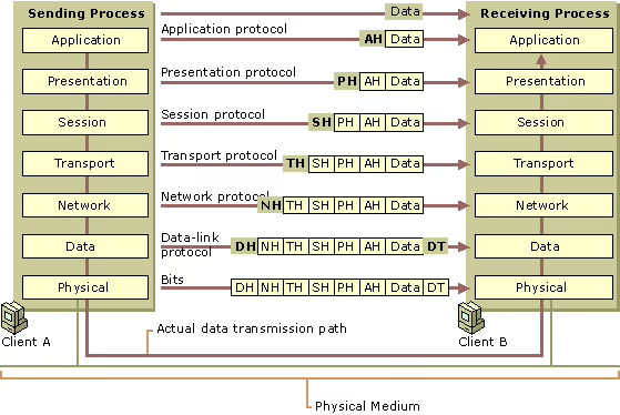
Visualizing the Layering Model
The OSI model illustrates how data traverses the networking stack:
Client A                                                  Client B
+-------+                                                +-------+
| App   |                                                | App   |
|  AH   |                                                |  AH   |
+-------+                                                +-------+
| Trans |                                                | Trans |
|  TH   |                                                |  TH   |
+-------+                                                +-------+
| Net   |                                                | Net   |
|  NH   |                                                |  NH   |
+-------+       +-------+       +-------+                +-------+
| Link  |       | Link  |       | Link  |                | Link  |
| DH DT |       | DH DT |       | DH DT |                | DH DT |
+-------+       +-------+       +-------+                +-------+
| Phys  |-------| Phys  |-------| Phys  |----------------| Phys  |
+-------+       +-------+       +-------+                +-------+
               Router/Switch   Router/Switch
Where:
AH = Application Header
TH = Transport Header
NH = Network Header
DH = Data Link Header
DT = Data Link Trailer
Notice that:
Headers are added at each sending layer and removed at each receiving layer
Only the Data Link layer typically adds both a header (DH) and trailer (DT)
Intermediate devices like routers and switches operate at different layers:
Switches typically work at Layer 2 (Data Link)
Routers operate at Layer 3 (Network)
When a packet travels across multiple networks, the Data Link headers and trailers are stripped and recreated at each hop, while the Network headers persist end-to-end. This behavior reinforces why trailers make sense at the Data Link layer but are unnecessary at the Network layer.
Practical Takeaways
If you're working with networking protocols or designing your own communication protocol, consider these key insights:
Use trailers when:
You need robust error detection for unreliable physical media
You're dealing with raw bit streams that need explicit delimitation
Processing needs to happen as data arrives (streaming fashion)
Hardware efficiency is critical
Stick with headers when:
You can include explicit length information
You're building on top of already reliable lower layers
Protocol processing happens after complete reception
Simplified processing is more important than byte-level efficiency
Error detection strategies:
Choose CRC for detecting transmission errors in raw bit streams
Use checksums for reasonable protection with lower computational cost
Implement end-to-end checks when reliability is critical
Avoid redundant error checking across layers
Exercises for Deeper Understanding
Implement a basic frame parser in Python:
Parse an Ethernet frame from raw bytes
Extract the header information
Verify the CRC in the trailer
Extract the encapsulated IP packet
Simulate bit stuffing:
Write a function to apply bit stuffing to a byte sequence
Write a corresponding function to remove bit stuffing
Test with sequences containing potential delimiter patterns
Analyze real network traffic:
Capture packets using Wireshark
Examine the relationship between frames and their encapsulated packets
Verify the CRC calculations for several frames
Observe how length fields in IP headers correspond to actual packet sizes
CRC calculation challenge:
Implement a CRC-32 calculator in assembly language
Compare its performance with a table-based approach
Verify your implementation against standard CRC-32 test vectors
Summary
The presence of trailers in frames and their absence in packets reflects fundamental differences in how these protocols operate:
Frames need trailers for delimitation, error detection, and efficient hardware processing as they interface directly with physical transmission media
Packets don't need trailers because they include length fields in their headers, rely on lower layers for error detection, and follow the end-to-end principle for reliability
This design distinction isn't arbitrary but rather a carefully considered trade-off that balances performance, reliability, and implementation complexity at each layer of the networking stack.
Understanding these design choices provides insight into how network protocols evolved and why they operate the way they do. Whether you're debugging network issues, implementing protocol stacks, or designing your own communication protocols, these principles remain relevant even as networking technology continues to advance.
References
IEEE 802.3 Ethernet Standards
RFC 791: Internet Protocol
RFC 793: Transmission Control Protocol
"Computer Networks: A Systems Approach" by Peterson and Davie
"TCP/IP Illustrated, Volume 1: The Protocols" by W. Richard Stevens